One of the most simples engines for to do in home with a simple crankshaft is the horizontal engine, a design where the displacer is commonly horizontal and the power piston in vertical.

Today we show you how to build a model like of the picture, step to step, with the main measures and tricks for that your machine will be a succesful.
The materials.
List
-An old Cd.
-Corrugated can of medium size (95 mm of diam).
-Canister of steel 55 mm diameter.
-Canister of aluminum with a diameter slightly fewer than the steel canister. (about 50 mm diam)
- Great can of 155 mm of diam.
-A good glue and epoxi for high temperature.
-Two medium cans for the burner of 65 and 75 mm of diam.
-Small tube of aluminum, steel, of 25 mm diameter, (from a stick of broom, brush, etc)
-Several canisters of aluminum
-Several pieces of metal, steel for to make the frame of the engine.
-Severals screws, nuts, washers, of 4 (about 30 pieces and of differents lenghts) and 3 mm diam ( about 2 pieces).
-30 centimeters of plastic tube that hold the suction of 9 mm inner diameter. ( used in buildings for measure levels, available in any hardware store.
-An a dipolo antenna.
-An open-eyebolt of medium size, an electrical strip.
-Optional items:
-Tin and tin solder.
-A small bearing.
and let's go!
The displacer.
 |
| Cani of aluminum with 50 mm diam. |
-Take a aluminum canister with a diameter of 50-52 mm and to burn slightly and erase all the paint with steel's wool, this avoid in the future bad smells when you start your machine. With a punch make a hole 82 mm from his bottom and cut the piece with a metal scissors. The final piece must have 80 mm of lenght. Cut it with care and file the edges with a file abrasive.
 |
| Dipolo antenna |
-With a dipolo antenna from an old appliance or bought in a electronic store, cut with a hacksaw a segment of 110 mm without squash or blend it. Use preferably the second segment or the third of the antenna for our use. Don't throw away the rest, it will be useful for the sealing of the displacer cylinder.
 |
| Aluminum can |
-From aluminum can cut the top with a metal scissors and make a hole in the center with a punch without hurry and carefully, this is critical item in our machine.
 |
| Typical epoxi for high temperature |
-Now we join the three parts with epoxi for high temperature, (more than 120ºC), first the wire with the top, leaving 5 mm in the interior of the displacer for to glue better our rod to the top. You should assure that the rod have a vertical position with respect the top. After several minutes we follow pasting the top with the rest of our displacer. The displacer must be airtight but don't exceed with the epoxi because our item must weight not more than 30 grs. The final piece should like this.

Displacer Cylinder.
 |
| Canister of steel 55 mm diameter. |
-We make our displacer cylinder mainly using a canister of 55 mm diameter. First clean and file all the outer painting. Next cut it 133 mm from its bottom like you did in the displacer, getting a nice cylinder like there is below of this text if you have been careful.

 |
| Top of the displacer cylinder |
-The top of the canister that you have cutted is very useful for to make a top for our cylinder. Cut the top and retire all the plastic items. Drill a hole of 10 mm in one side, this hole will have a small tube for the pass the air to the power piston.

-The following steps for the top of our cylinder are severals but very
easy. First of all take from the sidelong of a great can a big piece of steel.
 -Make a rectangle of 25 x 12 mm, this will be used for to make the tube that connect the displacer cylinder to the power cylinder.
 -A square of 35 x 35 mm is needed too for to hold the small tube that we get for our displacer. The square have a hold drilled for to support the third step of our antenna.
-A rectangle of 35 x 30 mm is used for to join the square made before to the rest of our top.
-A small square of 10 x10 mm with a hole for the third step of the antenna is suitable for to achieve a better junction.
 -For our machine we employ the second step of the antenna like axis and the third like seal and support for the axis. Cut a piece of 45 mm lenght with care. You notice that the part where the third step end and start the second is a good seal so that we count 45 mm from this edge. (View the arrow in the image) This edge is set in the interior part of our top. File the hole of our top if is necessary for to put it.
-Join the pieces with tin or epoxi according your preferences, the final item must be like this. Note that the sealing is set up in the interior of the top. The small rectangle of 10 x 10 mm ( no observable in the photo) is used for to obtain a better junction of the interior tube.
 |
| Corrugated can of medium size (95 mm of diam). |
-A cooling system is needed for our machine, you can make one with two corrugated can of medium size. One is used for to cut its bottom and the second for to make the frame of the cooling. You can proceed of the next form. Cut it one the bottom and make it a hole for to enter the canister of steel of 55 mm diameter. This is an ardous task so take care for not to spend too much glue or tin in the future.
 |
| Ring |
-"The ring" that you obtain must be drilled in three points for to set it three screws of 4mm diam and a length of 40mm. These screws allow you to hold the displacer cylinder very strong to the frame of the engine. Use washers both sides and a nut for to fit them to the ring. You can add something of glue to the screw for a more strong press.
 | |
| Joining the cooling to the cylinder. | (not ended) |
-Now, with the second can we cut it 45 mm from its bottom and we make a hole for the entrance of the displacer cylinder of 55 mm diameter. Also we drill a hole of 10 mm in its surface for the entrance of the water when the machine its running. For to join the parts use tin and a tin solder or epoxi if you want. Have in mind that the hole for the entrance of water must be vertical with respect the screws as you can see in the photo. The distance between the edge of the cylinder and the ring that support the screws is 10 mm exactly.
 |
| Stop flame |
-It's very recommendable for the sake of the pieces joined, to add a stop-flame. For that we get a second big can and we cut it the bottom, making a hole of 55 mm diam in its center too.
 |
-The final step for to finish this part of the machine is putting inside the displacer and close the top with the rest of the cylinder. Be careful with the position of the top for the displacer doesn't friction with any part of the cylinder. You can check the correct sealing of your displacer cylinder dipping it in water and blowing yourself for the small tube of connection. The absence of bubbles is a good signal, nevertheless avoid that enter so much water in the cylinder because you must expel after, for a good working is essential there isn't any water in the interior of the cylinder. Before to continue with the rest of the machine is very convenient that you respond yourself the following test for to avoid troubles in the future.
TEST 1.
1. Is your displacer hermetic?
2. Your displacer weight less of 30 grms?
3. Is the movement of your displacer smooth and without frictions?
4. Filling the cooling with water, there aren't water leaks, is this correct in your item?
5.Diving the item in water and blowing by the tube, there aren't any bubbles, correct?
If all the questions are answered with yes, go ahead!!!
 |
| Plastic tube |
-The tube of connection is maybe one of the weak point because creates a large dead space in our design, nevertheless this type of machine have like strong point its crankshaft that is very easy of to make. For our engine cut 19.5 cm of flexible plastic tube with a inner diameter of 9 mm. This plastic is very popular in the hardware stores for to measure the level in labors.
Power Cylinder.
 |
| Mop stick |
-For the power cylinder we need a aluminum tube of 22-25 mm of diameter, the best source for this are the sticks of brooms, brush, mops, etc. With a hacksaw cut a piece of 60 mm of lenght. Assure yourself that the piece is smooth for the interior and there aren't any imperfections.
-From any piece of steel can that leave you before, cut a rectangle 

of 120 x 40 mm, cut and file the edges and the corner that would be harmful for your fingers in the future. Make two small holes of 4 mm diam for the screws and and hole of 9 mm diam for the tube connection like you see in the photo. The situation of the holes are not critical but seeks that looks the photo. This is the base that hold our power cylinder.
 -Making a rectangle of 25 x 12 mm for the tube connection like you did in the displacer cylinder and solding to the base with tin or epoxi, previous folding the base to the power cylinder and mantaining with a screw of 4 mm with washers both sides and nut. The bigger the washers as the better sealing you have in your item.
-The next step for our cylinder is to reduce the dead space in the bottom of our cylinder with preferably with epoxi and cut a small piece of steel that covers the bottom and is joined to the bottom too.
 |
| The power cylinder ended. |
- For to end cover the line between the cylinder and the base with some of glue for to improve the sealing. ( The edge showed with a red arrow). The triangle formed after fold the base is a critical point too ( indoor of the red circle) fill it with epoxi or tin and glue if it is necessary. When you blow the air throught the small tube, the only exit must be the cylinder. Check this diving a little the piece in water and blowing yourself with the help of the connection tube that you did before.
 |
| An example of a good glue |
Power Piston.
 |
| A good power piston finished. |
-Epoxi is the best material for to do our piston, take a piece of 25 or 30 mm of the same stick that you get for the power cylinder and cover it with some of oil, that unables the epoxi glue itself at the wall of the cylinder. Use a good portion of epoxi now for to fill the cylinder, (our power piston has 20 mm of lenght) Wait that be harden in a few minutes and retire very carefully. You must check that the piston is too fit to the cylinder and it's almost sure that you should file little its surface with an abrassive paper very fine-grained. The optimal piston is that down with its own weight in a vertical situation and that get up with only the effort of your blow throught the cylinder. Furthermore is essential that shouldn't any clearance between the piston and the cylinder, because that unusable all our work.
 |
| A view of the bottom of the piston. |
-A hole for to a screw of 3mm in the center of our cylinder must be drilled with the usual electric drill and a small washer and two nuts will used for to join the piston to the shaft. When you did the hole for the screw, take a broach some bigger for to make a major hole but with few deep for the top of the screw not be a trouble.
 |
| Rectangle of 15 x 5 mm. |
-With a aluminum can that you have there, cut a big piece and drill three holes for a screw of 2.5 or 3 mm diameter. The distance between each hole must be 6 mm, and once you've drilled the holes, cut the rectangle of 15 x 5 mm. File the sharp edges like the photo.
 |
| The shaft finished without the piston. |
-Folding the previos rectangle and adding it a small screw of 2.5 or 3 mm of diam, with a lenght of 4 or 5 mm is the most light and strong solution for our power piston. In the image you can see the shaft finished without the piston. Now the last is join with the screw the epoxi piston to the shaft and the piece is finished. If you have a scales near, the power piston finished shouldn't weight more than 25 grms.
 |
| Power piston finished. |
-Like that the other pieces of the machine, we suggest you to do the next test for to check the working of your cylinder and power piston.
TEST 2.
1. Is your power piston weight less than 26 grms?
2. Can the power piston move smoothly through the cylinder?
3. Does the power piston down with the gravity force?
4. Can you move the piston by yourself without more effort blowing through the tube connection?
5. Are the leaks of air in your cylinder nonexistent with some of glue and epoxi? Check this with the water diving proof.
If you answered all this questions with a Yes, follow with the nexts steps.
The burner.
 |
| Two medium cans for the burner of 65 and 75 mm of diam |
-Is important for the correct running of our machine to have a burner that provide a good fire and for it we get two steel cans, one of 65mm diam and 65 mm of lenght, and second can of 75 mm diam and 55 mm lenght. In other words our burner has a lenght of 125 mm.
 |
| A top view, see the screw with the washer. |
-We retire the paper of the two cans and we join both with a hole drilled in the center of each one.
 |
| The burner finished. |
-And this the appearance of our burner ended.
The flywheel.
 |
| An old CD. |
-This item is very easy of to make if we get the necessary parts, for that we need an old Cd, a screw of 3mm diam and lenght of 25 mm, two washers and a nut for this screw. The washer must be big and thin. Also a screw for a screw of 4 mm, used for to avoid frictions between the flywheel and the frame of the machine. A washer for a screw of 6 mm diam with a weight of 14 grms, is very convenient for to balance the movement of our flywheel when the rods are linked.
 |
| A washer of 6 mm. |
 |
| Ball bearing. |
-The ball bearing for a screw of 3 mm diam can get from an old appliance; but it that if not your case you can buy it in a fishing store or an specialized shop in bearing in your city or more easy, through internet in anywhere.
-Use the files for the maximum adjust.
-With a good blow with a hammer the hole decrease a few.
-For the final adjust you should fold some the piece with a pliers, (See the photo)
-Some of glue can help but don't wait miracles.
 |
| Details. |
-Ok, you already have the piece with the ball bearing joined. The following is to set the Cd with the screw of 3 mm, use two big washers for to join the CD to the screw and the nut. If you don' have two big and light washers make two yourself with a fragment of any aluminum can with a normal scissors.
Use the respective two washers for to set the ball bearing and one or two washers of 4mm too, to avoid the Cd friction with the fragment of steel. When you give a small touch to the flywheel, this should have 7 or 8 turns. Now for to can continue working with your flywheel you must have a frame for the machine and this is matter of the next task.
Making a frame.
 |
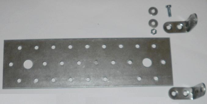
| Several pieces of metal,steel, etc. |
-The frame for your machine can be made with several materials, wood, cans, steel pieces, all depends on your imagination and the availability of the materials that you have. For my model I choose the classic fragments of steel that is sold by hardware stores for furnitures. There are cheap and you only need severals screws for to join it.
 |
| Screws, nuts, washers... |
-This type of construction is suitable for to make changes without troubles but you can have a different opinion or a better solution according to your interests. Anyway you should respect in your machine the nexts measures for the engine for a good working. Remember all the measures are in mm.

 |
| More pieces of steel |
-As you can notice in the photo is very convenient to assure the pieces properly, use nuts and screws where were necessary. The machine must have a horizontal position leved and the engine can't swing when it moves. Watch the nuts below the base, this doesn't touch the floor.

 |
| Electrical strip |
 |
| Eyebolt |
 |
| Detail of the use for eyebolt and strip. |
See here more views of the engine for to make the frame.
Following with the flywheel.

-Now the frame is terminated is time to continue with the flywheel, that is very easy, cut a small fragment of 20 x 6 mm from an aluminum can, fold it for the half, and drill two holes for a screw of 3mm diam.The correct position is seen in the picture. The goal of this item is to achieve that the angle amongst displacer and power piston be 90º degree and the while the stroke of the displacer be 20 mm and the power piston 10 mm.
 |
| Aluminum canister |
-Remember that for a good working of the system the flywheel should turn about 7 rounds when you slightly push it with your hand. Take a aluminum canister and cut from its sideway and cut a piece of 110 x 12 mm. Fold it in half and measure where you should make the holes for to connect the power piston to the flywheel. This operation is delicate and you must have two conditions in mind; The power piston must give the least dead space in its bottom part and the piston doesn't touch the bottom too, Both things reduce the power of our motor and should be avoid. The nuts can be problematic due to after fixed become to be leak so some of glue in the screw solve the trouble. By the way, mantain the 90º degree between the displacer and the piston and the last go linked to the screw in the fragment we made. The power rod oughtn't to tight in the links, should be a tiny space for it can move freely.
|
| Details. |
-The good perfomance of the power piston link show us that we can move it by blowing through the connection tube and so you should turn the flywheel almost without effort. Nevertheless you notice that there is a little hit when the flywheel is on with the power piston, like solution to this we add a washer for a screw of 6mm that weigh 14 grms plus some of epoxi that we use when we join the washer to the flywheel it serves for to balance the weight of the power piston and its rod. The washed is glued in the back side of the flywheel. Watch that the wash is opposite to the power piston, when the washer is the upper position of the flywheel, the power piston is in its lower position and vice versa.
|
 |
| Displacer shaft |
-Now for to link the displacer to the flywheel make a shaft like you did in the power piston and join it to the displacer rod with some of epoxi, the main screw that you put in the shaft shouldn't be very large for to make a light link.
-Likewise you did for the power rod, cut a fragment of an aluminum canister a piece of 90 x 12 mm, and fold it in half, measure and drill two holes for a screw of 3 mm. proceed like in the power rod, when all it is set it, check that the without the connnection tube set it, the engine can give a 1 turn or two with the push of your fingers. Finally set the tube connection and look las the machine turna with more difficulty, this is good because means there is a good sealing.Running the engine.
-Now the engine is finished and checked all the point that we have said in previos paragraphs, is time to start the engine, for the event, prepare before a bottle with cold water from your refrigerator, alchohol, cotton, paper and matchsticks.
|
| Machine ended. |
-First of all, crease the paper and set it in the interior of our burner to fill it,, the cotton must be in the upper position very near of the cylinder to heat. The next is to fill the cooling box with cold water and following the cotton with some of alcohol and turn on it with one matchstick. ( Be careful with the fire) After 30 seconds touch the flywheel in counterclockwise and the machine runs happily for two or three minutes, depending of the flame and the time last the water in the cooling in to heat it.
A video of the engine
Notes:
If all be do like in the page the machine should run without problems, otherway have always in mind the next critical factors; good sealing, low friction, low dead space, high temperature difference. The author doesn't be responsible of any accident or mishap that can happen. Work with care and attention.